


Fatigue Damage Assessment of Steel Structures
BY Eng. (Dr.) Chaminda S. Bandara
Introduction
Fatigue is defined as the weakening of a material caused by cyclic loading that results in progressive, brittle and localized structural damage. Present knowledge on fatigue of metals is at a very high level; however, research on fatigue behaviour of concrete and similar materials is still in progress. Most importantly, according to literature, 35% of failures of steel structures is due to fatigue (JRC report CEN/TC 250).
Fatigue damage assessment is considered an important part of the design of steel structures subjected to cyclic loading. The former BS 5400 – Part 10 (1980) and present EN 1993-1-9 (2005) are evidence for this. It is known that, in mechanical engineering, fatigue studies are very common and is one of the design criteria. However, this area is not frequently used in civil engineering in some countries including Sri Lanka. This fact emerged during a knowledge sharing session; therefore, I thought of sharing my knowledge on this subject with my colleague civil engineers. Accordingly, in this article, an attempt is made to introduce fatigue damage assessment methods and to compare the general procedure and the procedure given in design codes such as BS 5400 Part 10 (1980) and EN 1993-1-9 (2005).
Fatigue failure
Most civil engineering structures are subjected to cyclic loading in many ways. Bridges are subjected to moving vehicle loads, suspension bridges, towers and high-rise buildings are subjected to wind loads, structures open to the environment are subjected to thermal loads, buildings with machine floor are subjected to dynamic machine loads etc., and these loads make structures to oscillate/vibrate or have varying stresses and strains within them even without any oscillation or vibration. Fatigue is a failure at the material level and therefore, if a structure/component is subjected to cyclic stresses or strains inside the structure/component, there is a chance that fatigue failure may occur. Further, we know that the frequency of loading is different for different loads mentioned above. It has been verified that the loading frequency does not have considerable effect on fatigue except the effect of heating of the component if the frequency is very high. In summary, if any structure or a component is subjected to a cyclic stress or strain, that structure/component should be checked for fatigue.
Fatigue damage assessment
There are several methods used to assess the fatigue damage of a structure/component. The damage tolerant method and the safe life (total life) method are the two main methods. The damage tolerant method is associated with fracture mechanics whereas the safe life method is associated with the stress and number of cycles to failure (fatigue life) relationship of the material. Most of the design codes such as the BS 5400 – Part 10 (1980) and the EN 1993-1-9 (2005) use the safe life method. Further, the safe life method provides adequate accuracy for large structures. Therefore, the content of this article is limited to the safe life method.
One of the important aspects to look at in determining the fatigue failure possibility of a structure/component is the fatigue strength. Usually, fatigue strength is given as the stress amplitude or stress range required for a material to fail at 2 million cycles. A component made of a material with a high fatigue strength can obviously sustain a large number of high stress cycles before it fails. On the other hand, for most of the ductile metals, there is an endurance limit which is the limit of cyclic stress below which fatigue failure does not occur. It is to be noted that the endurance limit does not exist even for ductile metals under corrosive environment. Therefore, if the cyclic stress of a structure/component is known and if the fatigue strength, endurance limit etc., are known, the failure possibility and the fatigue life can be estimated. The simple tool that is used to estimate the fatigue possibility and fatigue life is the stress – life (S-N) curve which is a combination of the properties mentioned above. Figure 1 shows a typical S-N curve of a ductile steel. In this, the region of high stress and low number of cycles is called the Low Cycle Fatigue (LCF) region and the region of low stress and high number of cycles is called the High Cycle Fatigue (HCF) region. S-N curve of a material (Material S-N curve) is developed experimentally by conducting fatigue testing. Material S-N curves are readily available for most metals. If the S-N curve is available and the design cyclic stress amplitude is known, fatigue life can be directly obtained from the S-N curve subjected to the details discussed in the next paragraphs. When estimating the design stress, the stress concentration effect should be taken in to account.
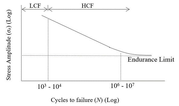
Figure 1 – Typical material S-N curve for a ductile steel
There are three major cyclic stress conditions observed in structures/components depending on the loading: (1) Constant amplitude, mean-zero stress cycles (the stress amplitude is constant for all the cycles and the mean stress of stress cycle is equal to zero), (2) constant amplitude, mean non-zero stress cycles (the stress amplitude is constant for all the cycles but the mean stress of stress cycle is not equal to zero, see Figure 2) and, (3) variable amplitude stress cycles (the stress amplitude is a variable and random in nature, see Figure 3) (Chaminda Bandara, 2015).
Usually the experimental S-N curves are developed for constant amplitude, mean-zero cyclic stress condition. If the structure/component is also subjected to this same cyclic stress condition, the S-N curve can be directly used to obtain the fatigue life. However, if the actual structure/component is subjected to a constant amplitude, mean non-zero stress cycles, a mean stress correction is required. The modified Goodman method is the most commonly used mean stress correction method. The modified Goodman equation is: σar = σa/(1-(σm/σu)) where, σar is the corrected stress and σu is the ultimate tensile strength of the material (Fuchs and Stephens, 1980).
If the structure/component is subjected to variable stress cycles, there can be a number of different stress ranges. In such cases, the rain-flow or the reservoir counting methods are usually employed to determine the stress ranges. A graphical explanation on reservoir counting method is illustrated in Figure 4. Then, the mean stress correction should be done. Finally, the fatigue damage caused by the different stress ranges should be added together to estimate the cumulative fatigue damage. For that, the Palmgren - Miner linear damage accumulation rule is generally used where, the total damage (D) is given by the sum of damages caused by each stress range ( D = ∑(ni/Ni), where, ni is the number of cycles applied under the ith stress range and Ni is the number of cycles to failure under the ith stress range ).
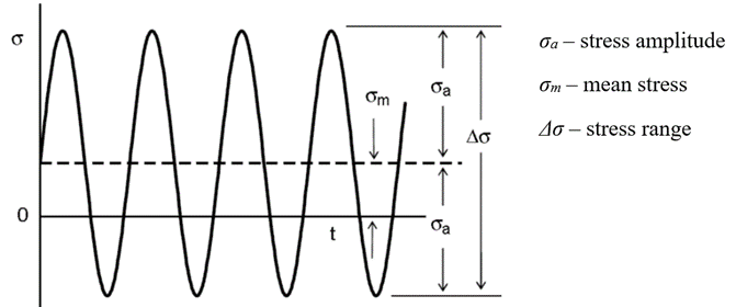
Figure 2 – Constant amplitude, mean non-zero stress cycles.
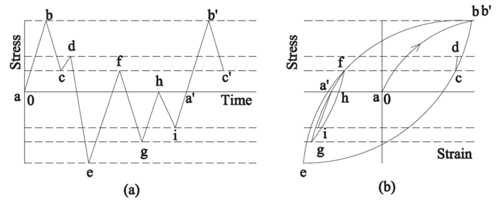
Figure 3 – (a) Variable amplitude stress cycle and (b) corresponding hysteresis loop.
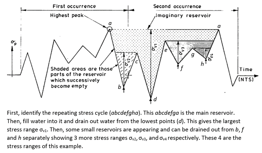
Figure 4 – Reservoir counting method (figure from BS 5400 Part 1 (1980) and modified).
The fatigue damage assessment method given in BS 5400 Part 10 (1980) and EN 1993-1-9 (2005) is the same approach discussed above, however, the S-N curves have been developed not only considering the material, but also the geometry of hotspots (high stress locations that are susceptible for fatigue crack initiation and propagation) and the stress conditions. Therefore, the S-N curves given in both these codes can be used without a mean stress correction and stress concentration effect. However, for variable amplitude loading, to count the number of cycles, the reservoir counting method has been recommended. Figure 5 shows set of S-N curves given in EN 1993-1-9 (2005) for steel. These curves are numbered from 160 to 36 called the detail category number. For example, 160 is the fatigue strength (160 MPa) of a plain steel member, 80 is the fatigue strength (80 MPa) of a bolted connection and 36 is the fatigue strength (36 MPa) of a critical welded joint, at 2 million cycles. These 3 detail categories are illustrated in the same figure (Figure 4) for easy reference. These detail categories are given in Tables 8.1 to 8.10 of the code. In the case of variable amplitude loading, to estimate the cumulative fatigue damage, both BS 5400 Part 1 (1980) and EN 1993-1-9 (2005) recommend the Palmgren – Miner linear damage rule. Further details can be found in both BS 5400 Part 1 (1980) and EN 1993-1-9 (2005). It should be noted that the fatigue damage assessment of complex systems may require modelling, simulations and testing.
Concluding remarks
Fatigue damage assessment is important for structures/components that are subjected to cyclic loading. Fatigue failures are mostly sudden failures if the propagation of cracks is not found and monitored. High cycle fatigue is common in structures that are subjected to relatively low stress cycles. Therefore, structures such as old steel railway bridges are usually checked for high cycle fatigue. Low cycle fatigue is common in structures that subjects to high stresses. The failure is expected at much shorter period of time. Therefore, structures such as towers/masts etc., located in high wind zones, are vulnerable for low cycle fatigue. A number of structural failures have occurred in Sri Lanka due to both high cycle and low cycle fatigue. Therefore, designing structures for fatigue and assessing existing structures is important. Designing for fatigue and assessing the fatigue damage of existing steel structures can be done using available codes of practice. It can be concluded that the code of practice EN1993-1-9 (2005) is a comprehensive guideline for fatigue damage assessment of steel structures and it can be used together with the Sri Lanka National Annex for fatigue (NA to SLS EN 1993-1-9 (2017)).
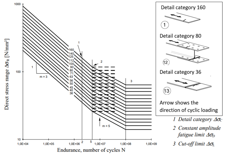
Figure 5 – Set of S-N curves given in EN 1993-1-9 (2005)
Reference
BS 5400 (1980). Steel, concrete and composite bridges: Part 10: Code of practice for fatigue, British Standards Institution, London.
Chaminda Bandara (2015). Fatigue damage assessment of steel structures and components – improvements in stress – life approach, Lap Lambert Academic Publishing, Germany.
EN 1993-1-9 (2005). Design of steel structures: Part 1-9: Fatigue, CEN, Brussels.
Fuchs H. O, Stephens R. I (1980). Metal fatigue in engineering, 1st Ed., John Wiley and Sons, New York.
JRC Report (2008), Assessment of existing steel structures: Recommendations for estimation of remaining fatigue life, Joint report CEN/TC 250, 1st Ed., European commission, Luxembourg.
Sri Lanka National Annexe to Eurocode 3: Design of Steel Structures - Part 1-9: Fatigue (2017), Sri Lanka Standards Institution.
 Eng. (Dr.) Chaminda S. Bandara
Eng. (Dr.) Chaminda S. Bandara has earned his BSc. Eng., specializing in Civil Engineering, MSc. Eng., in Structural Engineering and PhD in Civil Engineering from the University of Peradeniya. He is currently serving as a Senior Lecturer at the Department of Civil Engineering, Faculty of Engineering, University of Peradeniya.


