 |
|
Previous System
Above three pumps were powered by three phase 415 V, 200 kW induction motors. These motors were energized by the power panel shown in the Figure 8.2. Pumps were turned on and off by using push buttons. The starting method of these motors was using auto transformers and contactors. The auto transformer was used to limit the motor starting current. After the starting, these pumps run at full speed.
Figure 8.2 A Picture of Panel Supplying Power to a Pump in the Previous System.
|
|
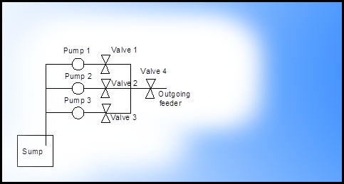
The total water flow rate had to be maintained at a value depending on the water usage of the consumers at the other end. Flow rate was adjusted for the required levels by manually turning the valves when pumps were running at full speed. Usually two pumps were running while one pump was kept idle. One pump could maintain a flow rate of 650-700 m3/hr. To maintain a flow rate of 1000 m3/hr (day time requirement), two pumps were turned on (running at full speed) with partially opened valves immediately followed by the running pumps.
The New System
The new system was implemented in innovative manner to improve the system efficiency using the cutting edge technology. The new system was designed and developed to fully automate the functions effectively.
Automated Functions
- If the water level of the clear water tank is low, pumps would be stopped after closing valves.
- Low water level, pump trip, breaker trip, pump running, pump stop, valve open, valve close, valve fault, harmonic filter healthy condition indications are provided.
- Required flow level can be entered using a touch screen (HMI device). Speeds of individual pumps are automatically adjusted to maintain the required flow rate.
- Pumps can be controlled using a HMI touch screen.
- Before stopping any pump, valve is closed.
- Before start any pump, system healthy check is carried out to verify supply voltage, clear water tank water level, pump condition, valve condition etc..
- If one pump is tripped, stand-by pump is started automatically to maintain the required flow rate.
- Surge protection, earth leakage protection
- Power monitoring
- Pumps can manually turned on using push buttons is required. Flow rate can also be manually adjusted.
In the previous system, pumps were started using auto transformers. Pumps were running at full speed while flow rate was maintained by manually closing valves. Instead, pumps are to be run at variable speed, controlled by 200 kW variable speed drives in the new system. Motorized valves are used. Valve opening direction is changed using forward-reverse contactors. Harmonic filters were connected for each VSD to mitigate harmonic input current. This new system is an improvement to the existing technology which was previously having in Kethhena water pumping station.
Cutting edge technologies were used for this work. For instance, variable speed drives were used instead of conventional motor starting methods such as using auto transformers. Proportional, Integral, Derivative (PID) control system was implemented for adjusting the flow rate. Programmable logic controller (PLC) is used to implement above automation requirements and to communicate between the HMI device and VSDs using an Ethernet switch as shown in the Figure 8.3. Ethernet communication protocol was used to keep communication between devices.
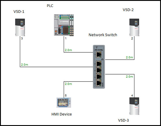 |
| Figure 8.3 : Communication Network |
Figure 8.4 shows the complete motor control panel developed adopting the cutting edge technologies. HMI device with touch screen was installed for data (flow rate, head, etc..) monitoring. Figure 8.5 demonstrates the mimic diagram of this system depicted in the HMI device.
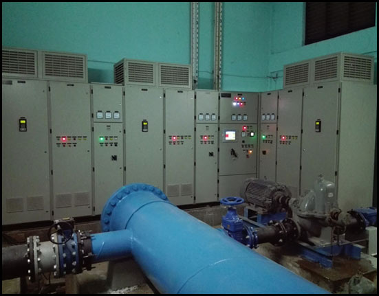 |
| Figure 8.4: Motor Control Panel |
| |
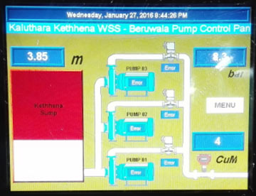 |
| Figure 8.5: Mimic Diagram of the Kethhena Beruwala Line Displayed in HMI |
Benefits of the New System
Due to the implementation of the new system, the necessity of keeping an operator around the clock in the panel room is eliminated. Valves are not needed to be adjusted by an operator. System condition can be remotely controlled and monitored so that water supply reliability is improved. This system was developed local engineers and technicians so that their confidence and expertise were greatly improved.
This work has reduced power consumption greatly. The new system is energy efficient compared with the old pumping system. After the implementing above system, around 42000 kWh of electricity was saved and peak demand has also dropped by nearly 100 kVA per month. As a result, nearly 29 Metric ton CO2 was saved monthly. The monthly saving in energy cost is around 0.55 Million SLR. The demand saving is nearly 0. 11 Million SLR. Hence the total monthly electricity saving would be around 0.7 Million SLR.
|